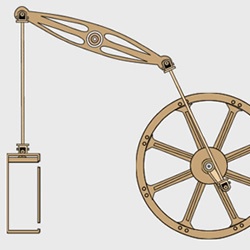
Moving A Pump With Physics
Tutorial Number: 170
Made with: Anime Studio Pro 9.2
Level: Intermediate
Animating this small graphic was made easy with the help of bones and physics. This tutorial gives a quick overview of how this was created.
Contents
1. Create the images
*Before you start this tutorial, I highly recommend you download the supporting content and play the animation.I used Adobe Fireworks, to create the images required for this tutorial, and saved them as .png files to maintain the transparency.
These images can be found in the Supporting Content

FIGURE 1-1 The 6 images required
2. Import and arrange images
1. Go to 'File' > 'Import' > 'Image...' then select all the images required. Importing the images into Anime Studio will result in each image having its own layer.2. Create a new group layer in the layers window, name it 'Pump' then move all the images into it.
Grouping all the layers into one group layer will help us later to move and scale the image with ease, and it's also required for the physics to work (Physics can only be turned on at group level)
3. Create two new bone layers in the group and name one 'Container' and one 'Images'. For this setup, all the images should be moved into the 'images' bone layer apart from the chamber image, which should remain outside.

FIGURE 2-1 Layers
4. Arrange the images so they look like Figure 2-2:

FIGURE 2-2 Images arranged in scene
3. Layer settings for physics
Open the layer settings for the main Pump group and enable the physics from the physics tab, then click OK. (FIGURE 3-1)
FIGURE 3-1 Layer settings for main group
Open the layer settings for the 'Images' bone layer, then go to the physics tab.
Make sure that 'Enable physics' is ticked, then tick 'Pivot on origin' and 'Enable motor', set the 'Motor torque' to 20 then click OK (FIGURE 3-2)

FIGURE 3-2 Layer settings for bone layer
Open the layer settings for the 'Container' bone layer and again go to the Physics tab, then tick the 'Non-moving object. (FIGURE 3-3)

FIGURE 3-3 Layer settings for the 'Container' bone layer
4. Adding Bones
The main bone on the wheel will rotate as a motor (Bone 1: FIGURE 4-1), moving the other bones. The rocker bone (Bone 3: FIGURE 4-1) has its tip locked so that stays in place and rocks. This setup also uses two bone layers, one for the pump, and another as a guide for the pump's up/down shaft - without the guides the up/down bone would instead swing side to side.
FIGURE 4-1 Bone Setup with images
Adding the bones to the 'Image' bone layer
1. Select the 'Images' bone layer, and then use the Add Bone
 tool and add the first bone for the wheel, moving from the centre of the wheel to the end of the arm (arm.png) (Bone 1: FIGURE 4-1),
 2. Next we create the first shaft bone, moving from the end of the arm to the right of the rocker (Bone 2: FIGURE 4-1),
3. Add the rocker bone, starting at the right of the rocker and ending in the centre (Bone 3: FIGURE 4-1).
4. Once the rocker bone has been added, use the Bones Physics
 tool (Step 1: FIGURE 4-2) and enable the 'Lock tip' setting for this bone (Step 2: FIGURE 4-2)
FIGURE 4-2 Enable 'Lock tip' for the rocker bone
5. The second shaft has a bone from the left of the rocker to the top of the pump. The bones strength has also been set to 0.3717 with the Bone Strength
 tool (Bone 4: FIGURE 4-1),
 6. The pump has a small bone to its left. This is used to keep the pump in place (Bone 5: FIGURE 4-1),
It's important to add the bones in the right order to ensure they are parented correctly. The first bone will become the motor and its 'children' will be moved by it. (FIGURE 4-3)
(The Reparent Bone
 tool would need to be used if not)
FIGURE 4-3 Bone setup with bone 1 as parent. The selected bone 3 has its tip locked
5. Bind Layer
We now need to assign each bone to the correct image layer:1. Select an image layer
2. Select the bind layer tool
3. Click on the relevant bone to bind

FIGURE 5-1 Bind Layer
6. Container bones
This is probably the only tricky bit that takes some trial and error.1. Two bones are added either side of the chamber
2. The bone strengths have been set with the Bone Strength
tool so that the pump's up/down shaft moves smoothly. You will need to adjust the position and strength to ensure this is working correctly. 
FIGURE 6-1 Container Bones
Supporting Content
Download Details
Zip File Size: 67KB
Last updated: 31 May 2013 04:40:35
Made with: Anime Studio Pro 9.2
File Name: anime_studio_tutor_files_170.zip
Last updated: 31 May 2013 04:40:35
Made with: Anime Studio Pro 9.2
File Name: anime_studio_tutor_files_170.zip
Rate This Tutorial
Once you have completed this tutorial, please give it a rating:
9 Rates
(4.6)
Comments
-
Member Since: 19 March 2013Last Logged In: 14 October 2015Comments: 8Tutorials Completed: 15
-
Member Since: 3 March 2010Last Logged In: 14 April 2024Comments: 134Tutorials Completed: 1057admin says:
20 June 2013 at 01:58:47 PMYou're welcome. The physics engine makes it so easy to animate, you could do it without, but it's not as fun. This could also be used for other things like trains or even a bike and rider.
-
-
Member Since: 23 July 2013Last Logged In: 16 September 2023Comments: 4Tutorials Completed: 4
-
Member Since: 3 March 2010Last Logged In: 14 April 2024Comments: 134Tutorials Completed: 1057
-
Member Since: 23 July 2013Last Logged In: 16 September 2023Comments: 4Tutorials Completed: 4
-
Member Since: 23 July 2013Last Logged In: 16 September 2023Comments: 4Tutorials Completed: 4
-
Member Since: 3 March 2010Last Logged In: 14 April 2024Comments: 134Tutorials Completed: 1057admin says:
29 July 2013 at 05:21:09 PMI'm sorry to see that you have been having problems.
It may well be a bug.
I've sent you an email to see if I can help resolve the issue.
-
Member Since: 23 July 2013Last Logged In: 16 September 2023Comments: 4Tutorials Completed: 4
-
-
Member Since: 18 November 2015Last Logged In: 23 April 2023Comments: 24Tutorials Completed: 68
-
Member Since: 1 May 2021Last Logged In: 8 April 2023Comments: 1Tutorials Completed: 0


Other Tutorials In This Category
-
 Creating Soccerball Physics4 Rates (3.8)
 -
 Fun with Physics7 Rates (4.9)
 -
 How to use physics in Anime Studio3 Rates (4.7)
 -
 Basic Physics1 Rating (5)

Please use the 'reply' button on a comment if you wish to reply to someone.